Technical Info
A QUICK OVERVIEW OF A CIRCULATOR
The Radio Frequency (RF) Circulator is a very unique device. It is a non-reciprocating passive device that performs a function that cannot be duplicated. A Circulator is a passive 3 port ferrimagnetic device that can redirect RF energy to an adjacent port.
Isolators by definition are Circulators that are provided with one of the 3 ports terminated so as to absorb reflected power.
There are 2 primary benefits to Circulators;
1. They will accept a very poor VSWR at the input and still provide optimal VSWR at the output.
2. Provides a low loss path from input to output while providing protection at the input port from reflected power by isolating the RF and directing it to a load on an adjacent port.
There are several common uses for Circulators. The more common are matching structures in an RF circuit, protection from antennas that become open, shorted or overloaded, and as a duplexer where a transmitter and receiver are sharing a common antenna.
Circulators have a variety of configurations based on the many variables that come into play when designing. The common variables being frequency, bandwidth, isolation, insertion loss, VSWR, power, altitude, IMD, operating temperatures, size, orientation, phase and group delay. The common varieties are waveguide, drop in, coaxial, microstrip, surface mount and hybrids (i.e. connector and tab on adjacent ports).
Circulators are used in a multitude of applications. Some being Cellular Infrastructure, Phase Array Radar, Public Safety Radio, Aircraft Doppler, Missile Guidance, WiMax Infrastructure, Point to Point Radios, Medical, Food Processing, Satellite, Signal Jamming, Test Equipment.
DROP-IN TEST FIXTURES
At Sonoma Scientific, all of our drop-in style units are designed and tested using quality 50 ohms microstrip fixtures. The actual physical characteristics of our fixtures vary based on frequency of their usage and the tab requirements of the devices being tested. A common problem in making measurements in microstrip media is the need to separate the effects of the transmission medium from the device characteristics. At microwave frequencies, systemic effects such as leakage, test port mismatch and frequency response affect measured data.
In microstrip measurements, it is difficult to build impedance standards that are easily characterized. For example short circuits are inductive, open circuits radiate energy and it is difficult to build a high-quality, purely resistive load. Typical problems in determining the parameters of the device being tested and having a significant effect on measured data include:
Impedance discontinuities occurring at the coax to microstrip launch. The reflection at this point is typically larger than that of the device interface.
The signal is attenuated in both the coax and microstrip portions of the fixture.
At Sonoma Scientific, we use a calibration method known as "LRL" as opposed to using a standard 12-term calibration. The LRL (Line-Reflect-Line) provides an enhanced capability for error compensation when making a measurement in microstrip, and currently provides the highest accuracy in measurements available today. The LRL calibration technique uses the characteristics of a length of transmission line as the calibration standard. A full LRL calibration requires two transmission line measurements, a high reflective measurement and an isolation measurement. Taking into account that there must be adequate separation between the coax/microstrip launches, (a minimum of two wavelengths are recommended), to avoid unwanted variations in error correction caused by the coupling of higher-order modes. Since microstrip is a dispersive media, the test equipment Sonoma Scientific uses applies dispersion compensation using specific microstrip parameters, these being:
Characteristic Impedance (Reference)
Effective Dielectric Constant Zc
Substrate Dielectric Constant
Thickness of the Substrate
Width of the Trace
Sonoma Scientific believes that by using this method we are providing the best possible environment for the testing of our drop-in units, allowing us to maintain the highest practicable quality and equaling or surpassing our customers’ requirements.
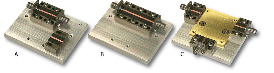
A. Fixture As Through Line Used For First Transmission Line Measurement
B. Fixture With Second Through Line Inserted For Second Transmission Line Measurement
C. Fixture Ready for Testing Units